Contents
Conceptual Aircraft Design
Electrified Aircraft Design-Space Exploration
Could electrification be the key to sustainable aviation?
When is it advantageous to use electrical components for aircraft propulsion?
How much on-board energy could be saved?
Which propulsion-system architecture and electrification level is best for which mission?
Electrified aircraft have the potential to significantly reduce the environmental impact of aviation, as well as the cost to operate the aircraft. Batteries, however, store much less energy per unit mass compared to conventional fossil fuels. As a result, an all-electric aircraft designed for the same mission as a conventional one would likely be prohibitively heavy. A trade-off thus exists between aircraft energy consumption, weight and the mission it is designed for.
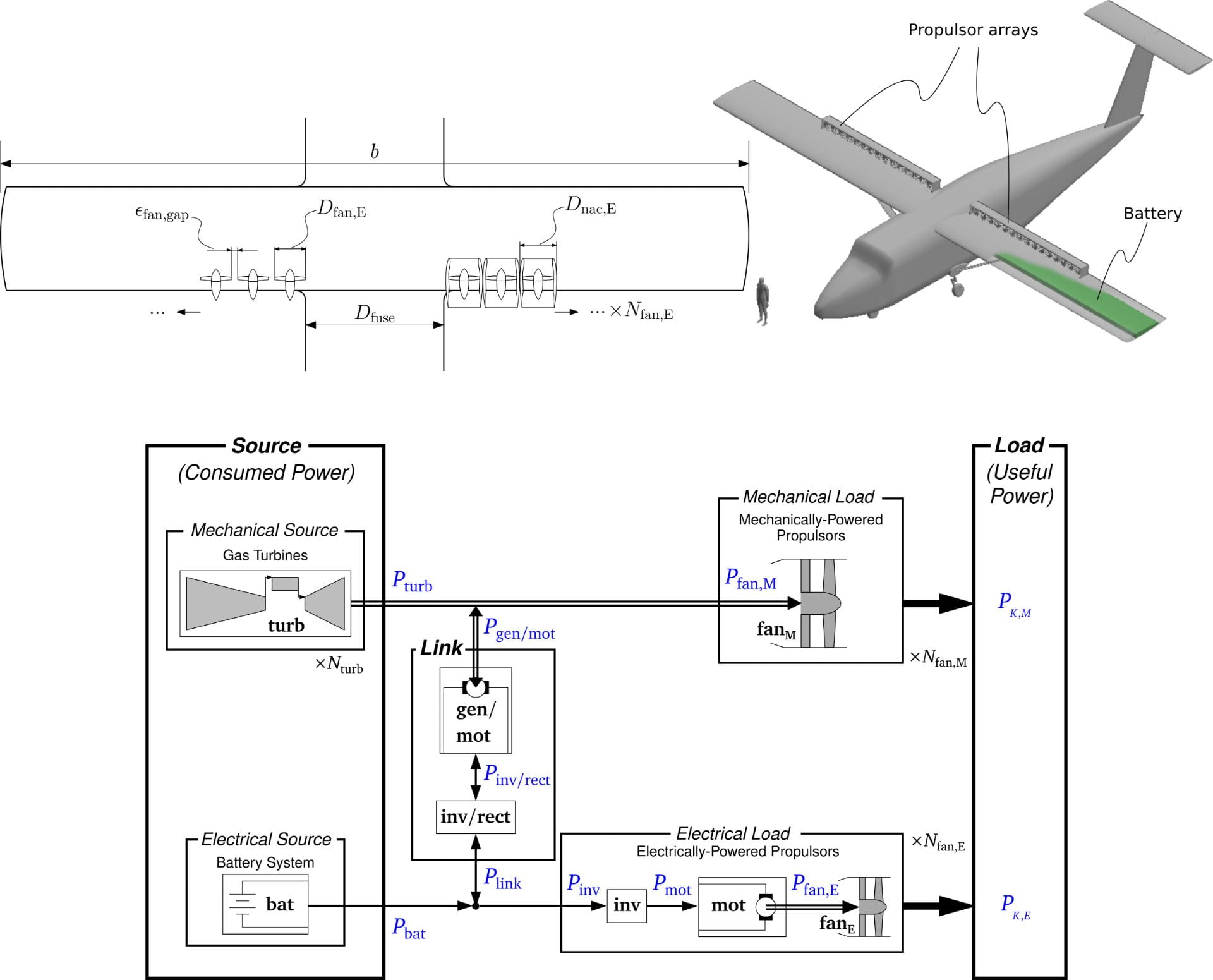
At the ADRL, we use computational tools to model a range of electrified aircraft (all-electric, hybrid-electric, turbo-electric) in order to understand these trade-offs. The tools that we are developing allow us to model the propulsion systems of these aircraft (as well as conventional turbojets, turbofans and turboprops) within a unified model in order to explore the large design space that exist for electrified aircraft, as well as accurately model the performance of individual point designs.
Our goal is to help guide the future of air transportation in a direction of sustainability and affordability.
Lead researcher : Michael Kruger
M. Kruger and A. Uranga, “The Feasibility of Electric Propulsion for Commuter Aircraft”, 2020 AIAA SciTech, Orlando, FL, Jan. 6–10. 2020. doi: 10.2514/6.2020-1499 Full PDF
M. Kruger, S. Byahut, A. Uranga, J. Gonzalez, D.K. Hall, and A. Dowdle, “Electrified Aircraft Trade-Space Exploration”, 2018 AIAA Aviation, Atlanta, GA, June 25–29. 2018. doi: 10.2514/6.2018-4227 Full PDF
Electrified Propulsion System Modeling
What kind of electrical component models are needed in aircraft-level performance estimates in order to accurately quantify the effects of electrification?
What propulsion-system component characteristics and operational scenarios are best suited for each mission segment?
What technological advances are needed for electrified propulsion systems to be feasible, and beneficial, for aircraft?
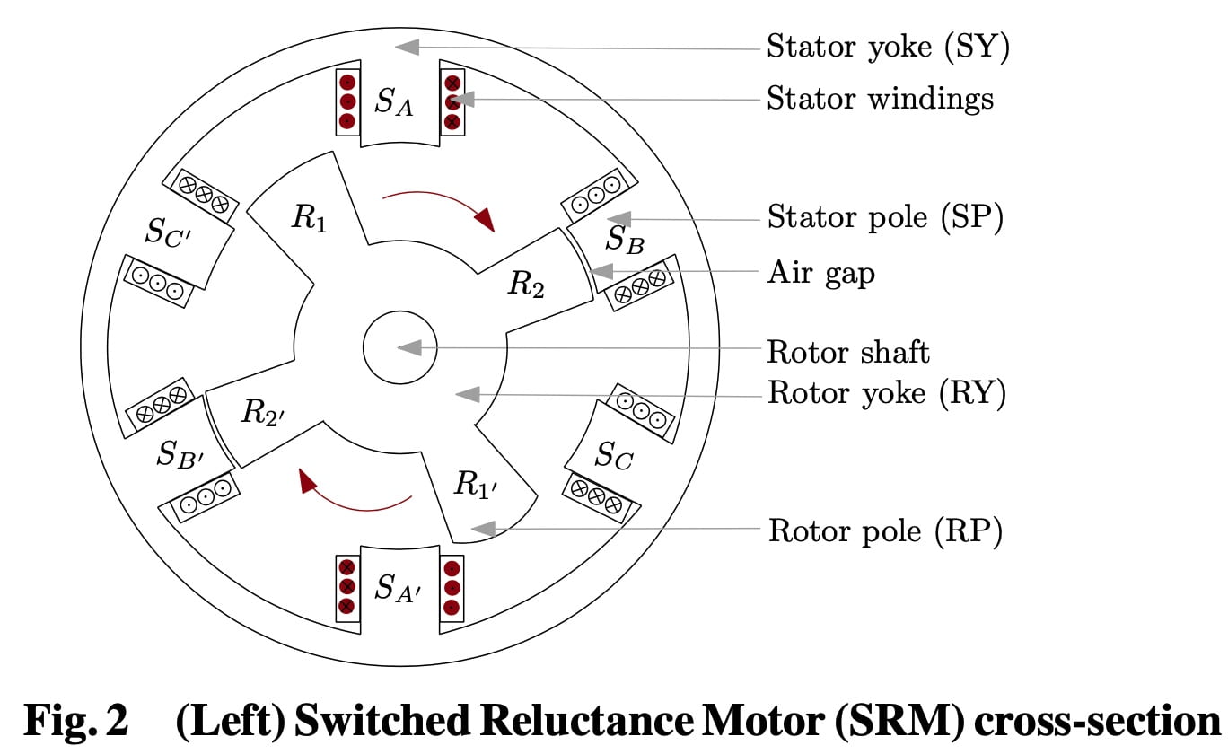
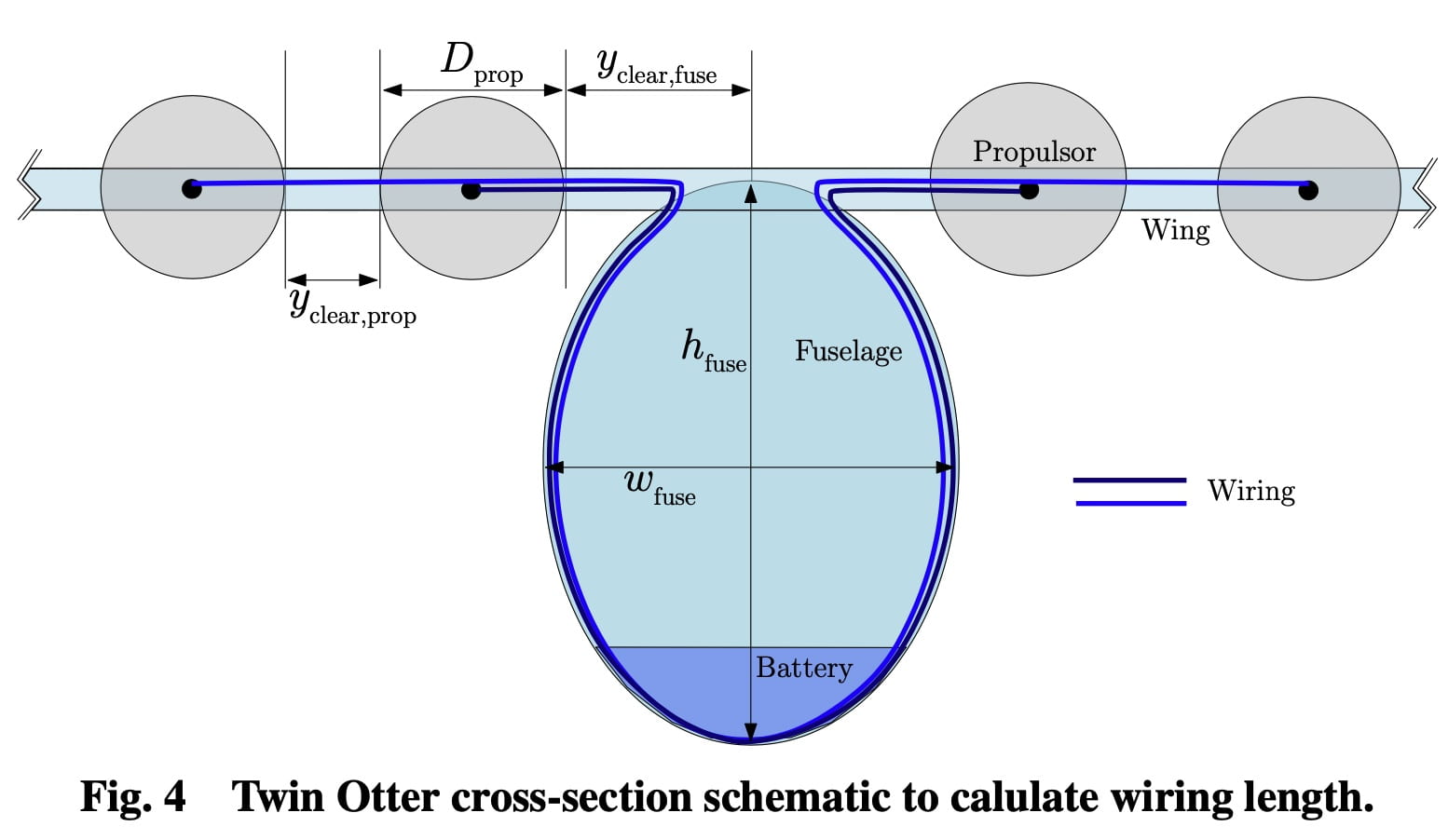
As part of the unified aircraft design framework, we develop models for the major components in an electrified propulsion system, including the battery, power converter, power distribution, wiring, motor, thermal management, and the propulsor (e.g. ducted fan). We explore how to size the electrical propulsion components to provide the required power for all the flight segments, while maintaining top performance during segments with lower power demand. This allows us to find the optimal, most energy-efficient, way to operate them along the mission. This in turn determines which propulsion system architecture (conventional, all-electric, or hybrid-electric and turbo-electric and their serial/parallel variations) and which level of electrification is best suited for which missions.
We also consider the physical and safety limitations involved in operating high-power electrical components in flight. Key to this is arcing, which occurs when conductors reach high enough voltages that the spacing or insulation between them becomes inadequate. At cruising altitude, this breakdown voltage threshold is lower due to the lower ambient pressure, and leads to a constraint for the safe in-flight operation of the electrical components. This consideration then influences the optimal operating voltage.
Technological advancements in electrical components are key to making electrified aircraft a reality. We consider historical trends, current state-of-the-art products, and cutting-edge research to determine a range of values for electrical component efficiencies, and specific energy and power (i.e. energy and power per unit mass), as indicators of technology level. We thus build technology-level scenarios, from conservative to optimistic, for near-term and long-term predictions.
In short, our research at the ADRL looks at how electrical components in a propulsion system behave under different power loads, and what is required in terms of technology and operational constraints to enable their adoption to reduce energy-usage of future aircraft.
Lead researcher : Saakar Byahut
S. Byahut and A. Uranga, “Power Distribution and Thermal Management Modeling for Electrified Aircraft”, 2020 AIAA/IEEE Electric Aircraft Technologies Symposium (EATS), Virtual Event, Aug. 26–28. 2020. doi: 10.2514/6.2020-3578 Full PDF
S. Byahut and A. Uranga, “Propulsion Powertrain Component Modeling for an All-Electric Aircraft Mission”, 2020 AIAA SciTech, Orlando, FL, Jan. 6–10. 2020. doi: 10.2514/6.2020-0015 Full PDF
Aircraft Configurations
Can a tool be developed to determine which airframe configuration, propulsion system, and technology combination is best suited for a specific mission?
Where in the aircraft design space does a specific technology offer the greatest advantage?
Why does a technology offer benefits for particular missions but not for others?
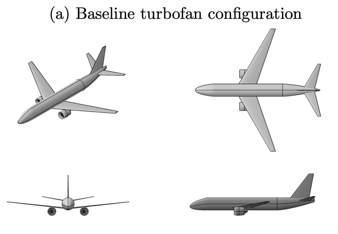
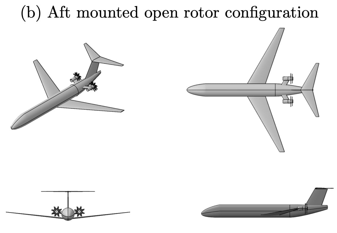
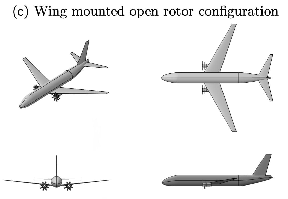
When researchers investigate the potential benefit of a “technology” — such as the electrification of the propulsion system, the use of open rotors, boundary layer ingestion, distributed propulsion, the use of a lifting fuselage or a blended-wing-body airframe — they usually focus on a specific aircraft mission, for example a tube-and-wing aircraft jet flying coast-to-coast. The conclusion of whether a technology is promising is then about the aircraft-mission-technology combination rather than the technology itself.
A better way to determine the potential benefit of a technology is to apply it to a wider design space, and meet the specific mission requirements while optimizing the aircraft configuration and propulsion system for that case. The designer can then determine that a technology offers the most benefit for a certain aircraft and mission, and can know for which configuration-mission cases the technology is ill-suited.
At the ADRL we are developing models and an optimization framework that allows us to perform this exploration for a wide variety of technologies. Our goal is to have a framework that can answer the following questions:
1) What is the mission and aircraft for which a particular technology offer the most benefit?
2) What is the best aircraft and technology to fly a given mission?
Such tool can be used by designers to determine which technologies to pursue given the mission requirements. Additionally, it can be used for researchers working on technologies to know which aircraft their technology is best suited for. Most importantly, this research framework tells both groups why.
Lead researcher : Andrew Dorsey
A. Dorsey and A. Uranga, “Design Space Exploration of Future Open Rotor Configurations”, 2020 AIAA Propulsion and Energy, Virtual Event, Aug. 24–28. 2020. doi: 10.2514/6.2020-3680
Engine Modeling for CFD
How can propulsors be modeled in high-fidelity CFD and design optimization of full aircraft with tight coupling between airframe and propulsion system?
Can a propulsor model capture the effects of a distorted non-axisymmetric inflow on propulsor performance?
What are the tradeoffs between engine performance and airframe aerodynamics in the coupled airframe-propulsor design optimization?
A challenge in the design of novel aircraft configuration with tight propulsor-airframe integration is that the best overall performance can only be realized by the simultaneous coupled optimization of the two sub-systems (propulsion and airframe). As a result, standard methods for the design of airframes on the one hand and engines on the other are not applicable. Representing a boundary-layer-ingesting (BLI) propulsion system within high- and medium-fidelity codes for full-aircraft multi-disciplinary simulations requires an engine model that is capable of (i) capturing the effects of a non-uniform inlet flow on the propulsor (airframe influence on the propulsor), and (ii) conversely representing the effect of the presence and operating point of the propulsor on the airframe flow (propulsor influence on the airframe), with (iii) a computational cost and level of abstraction (parameterization) that is compatible with design studies based on RANS-type CFD simulations. Such a model will enable the design of coupled airframe-propulsor systems and the prediction of their performance.
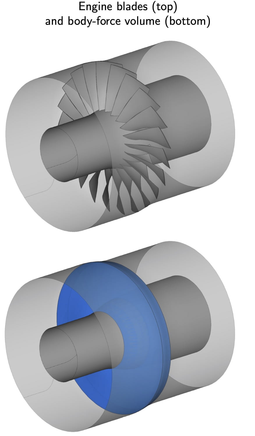
We have developed a body-force propulsor model that replaces the engine blades with a source volume to produce the equivalent flow turning, work input, and losses. The model is able to capture non-axisymmetric effects and only requires specification of the blade camber and thickness distributions. We built upon an inviscid formulation for the body-force that was capable of predicting the inviscid distortion transfer effects (Hall et al., Journal of Turbomachinery 2017), but which did not account for losses and blade metal blockage effects. The improved formulation with a blockage component that we developed is better able to predict the propulsor work. Furthermore, the addition of loss terms to model 2D profile losses and secondary flow losses allows us to predict propulsor efficiency. Our model is implemented in the open-source flow solver ADflow (originally developed by the MDO Lab at the University of Michigan) and has been validated against experimental data.
Lead researcher : Tianbo (Raye) Xie
T. Xie, and A. Uranga, “Development and Validation of Non-Axisymmetric Body-Force Propulsor Model”, 2020 AIAA Propulsion and Energy, Virtual Event, Aug. 24–28. 2020. doi: 10.2514/6.2020-3686
Low Reynolds Number Flows
Exploiting 3D Effects: Tubercles
How does the use of leading-edge tubercles in a low-Reynolds number wing affect its aerodynamic characteristics?
Which flow structures are generated by such a wavy leading edge geometry, and what physical mechanisms are responsible for the changes in performance?
Can the resulting wing’s three-dimensionality be exploited to increase aerodynamic performance?
The design of low-Reynolds number wings is challenged by the high sensitivity of the flow in this regime to disturbances (whether external or geometrically-induced) and the need to achieve high aerodynamic performance with flows that tend to remain laminar over a large extent of the wing and thus are prone to separation. The highly non-linear nature of transition to turbulence, often following separation, also makes the prediction of performance using analytical methods difficult.
In order to increase the design space for low-Reynolds wings, the use of non-straight leading edges has been introduced. The use of tubercles is such a modification, inspired by the fins of humpback whales. In a ‘tubercled’ wing, the chord length and/or the airfoil shape are varied continuously and smoothly in a periodic pattern along the span. The trailing edge of the wing serves as the anchor of this transformation, resulting in a wing which appears to have knuckles along the leading edge.
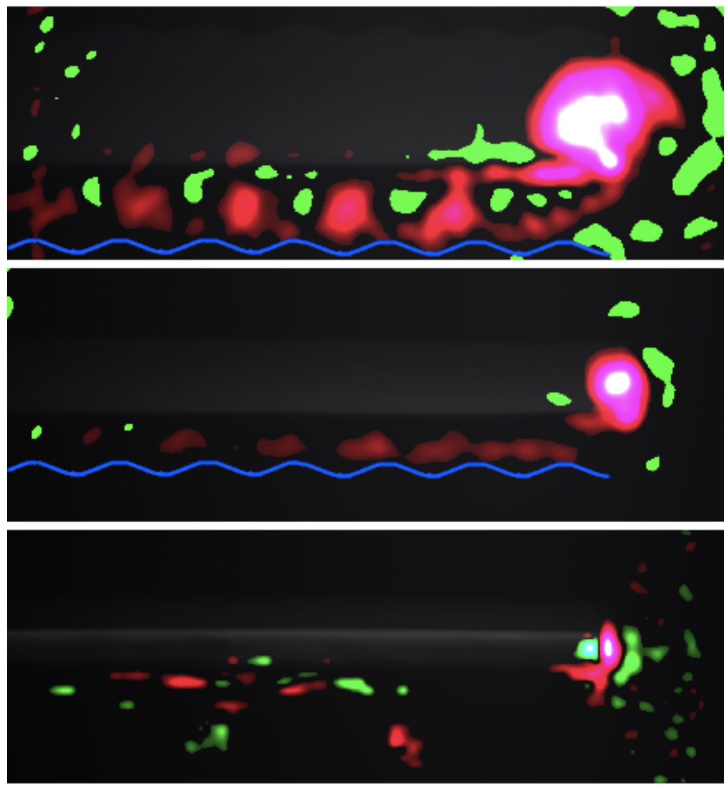
Previous studies have tried to quantify the effects of these tubercles relative to a standard wing of the same average chord. In the low Reynolds number regime (10k-500k), which is relevant to many birds and small or medium-sized air vehicles, some researchers have found that tubercles increase lift, increase stall angles, and reduce drag, while others have observed the opposite. We are working to determine whether the use of tubercles in wings for small flyers can increase maximum lift with a gain in aerodynamic performance (lift-to-drag ratio) compared to a baseline straight rectangular high-lift wing. More importantly, we aim at determining which physical mechanisms are responsible for the changes in performance, and whether they can be favorably exploited to increase performance. This research is being carried out experimentally in USC’s low-turbulence Dryden Wind Tunnel using a combination of force measurements, wake surveys, and Particle Image Velocimetry (PIV).
Lead researcher : James Croughan
Transition Prediction in CFD
Can a physics-based transition model be constructed to capture natural transition to turbulence in a variety of applications using RANS simulations?
How can transition prediction be improved without relying on correlations?
What are the core physical mechanisms that need to be modeled in order to capture natural transition phenomena?
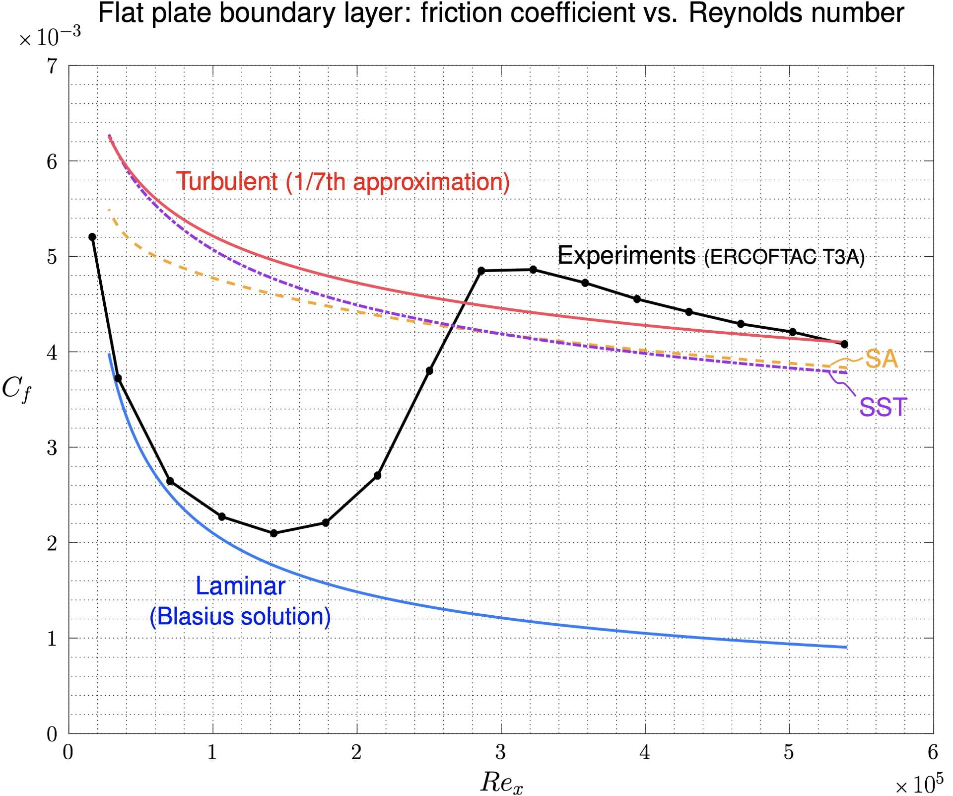
One of the most challenging and unresolved problems in the field of fluid mechanics is the prediction of transition to turbulent flow in three-dimensional applications. The ability to predict transition is crucial to the prediction of aerodynamic performance, and is also linked to the prediction of separation and reattachment. While DNS and LES type simulations can generally accurately predict transition, their high computational cost renders them prohibitive for design studies, as well as for most moderate to high Reynolds number flow applications. It is thus expected that RANS-based Computational Fluid Dynamics (CFD) simulations will remain a primary tool for aerodynamicists for many years, but their unreliability when it comes to transition remains a major obstacle.
At the ADRL, we are developing physics-based transition models that can be coupled with standard RANS turbulence models in order to improve the prediction of flows in which natural transition plays an important role. The goal is for these models to be as general as possible, and therefore avoid the use of empirical correlations which are usually limited to particular flows. While whether such models are actually possible remains an open question, we are working on pushing the boundaries of what they are capable of.
Lead researcher : Arturo Cajal
